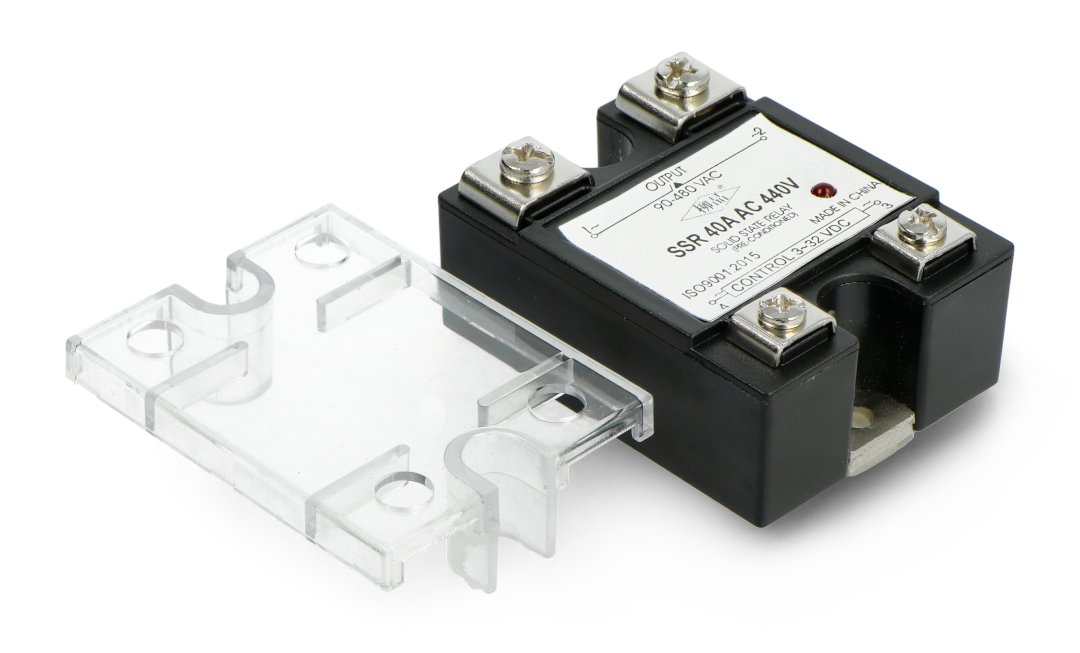
A TRIAC (Triode for Alternating Current) is a three-terminal, bidirectional semiconductor device used as the primary switching element in most AC solid-state relays (SSRs). It functions as an electronic switch that can conduct current in both directions, making it ideal for controlling alternating current loads such as lamps, motors, or heaters.
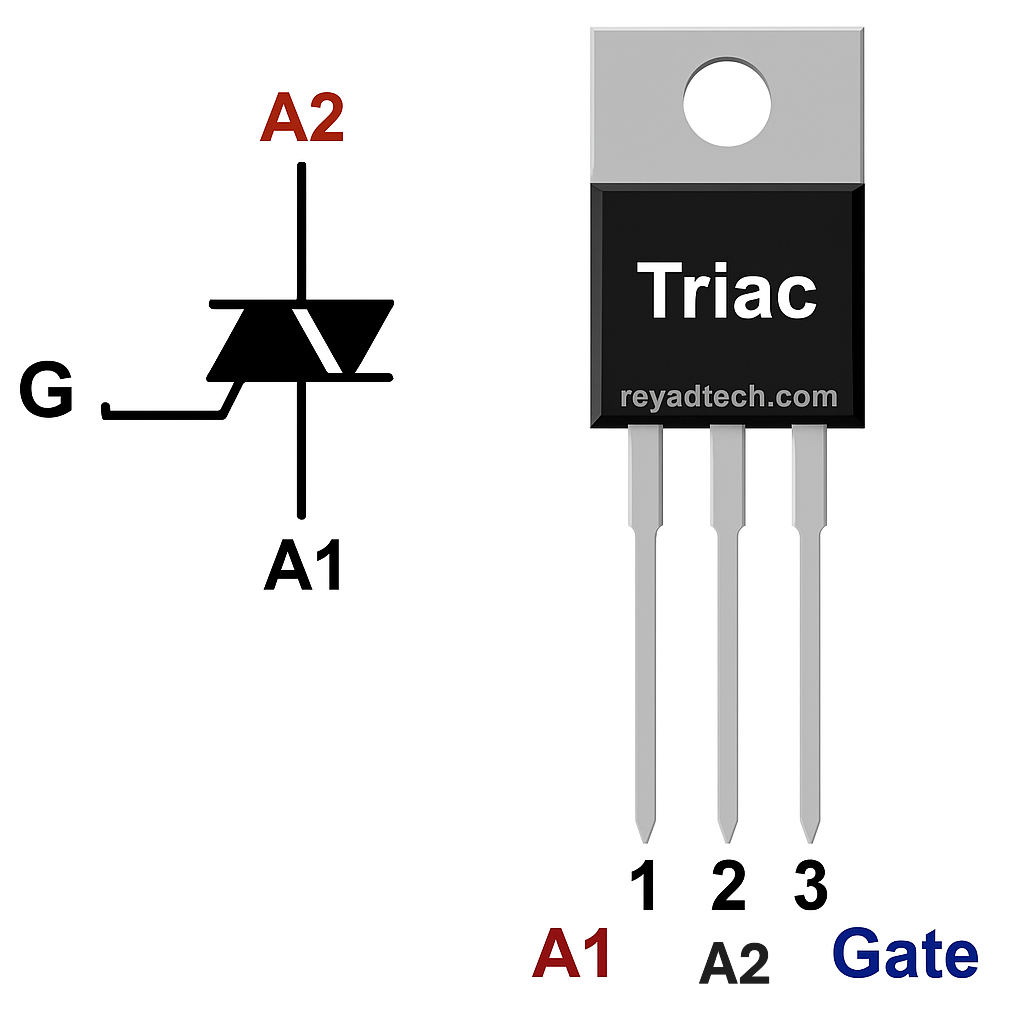
Structurally, a TRIAC behaves like two silicon-controlled rectifiers (SCRs) connected in inverse parallel, with their gates coupled. It has three terminals: Main Terminal 1 (MT1), Main Terminal 2 (MT2), and Gate (G). When a triggering current is applied to the gate — under the correct voltage conditions between MT1 and MT2 — the TRIAC enters a latching ON state and begins to conduct AC current.
In the context of an SSR, the gate is typically activated by a phototriac embedded in an opto-isolator such as the MOC3041, which provides safe, galvanic isolation between the low-voltage control circuit and the high-voltage AC load.
From a semiconductor physics perspective, the TRIAC is a four-layer (PNPNPN) device and can be triggered into conduction in all four quadrants of operation, depending on the polarity of the gate and MT2 voltage with respect to MT1. This allows for versatile triggering conditions, though in SSRs the most common and stable configuration is quadrant I or III, where MT2 and gate are positive or both negative relative to MT1.
Because TRIACs support bidirectional conduction and zero-cross turn-off, they are especially suited for AC switching applications. However, they require careful gate triggering conditions and protection against dV/dt false triggering, which is often managed with a snubber network (a resistor and capacitor in series across MT1–MT2).
In summary, the TRIAC in an SSR enables safe, fast, and silent control of high-voltage AC power using a low-energy signal, and its intrinsic behavior aligns perfectly with the natural properties of AC systems, making it the core of reliable solid-state power switching.
🔹 What is the MOC3041?
the MOC3041 is a specialized type of optocoupler, also referred to as an opto-triac driver, designed for AC switching applications. It is primarily used to interface low-voltage DC control circuits with high-voltage AC loads, offering complete galvanic isolation between the two sides. This isolation is essential in applications where microcontrollers, logic gates, or other sensitive electronics are used to control AC-powered devices.
Internally, the MOC3041 contains two main components within a single 6-pin DIP package:
- An infrared light-emitting diode (IR LED) — located on the input side.
- A phototriac detector — on the output side, triggered by the light emitted from the LED.
When a current flows through the IR LED (typically triggered by a 5V logic signal), it emits infrared radiation. This light travels across an optically transparent but electrically insulating gap and is received by the photosensitive triac. The phototriac becomes conductive when illuminated, allowing a small AC current to pass between its terminals. This output is then used to trigger the gate of a larger, external TRIAC that handles the actual AC load current.
What makes the MOC3041 especially suitable for mains power control is its built-in zero-crossing detection circuit. This internal circuitry ensures that the phototriac will only turn on when the AC line voltage is near zero volts — the zero-cross point of the AC waveform. Switching at this point significantly reduces electrical noise, electromagnetic interference (EMI), and inrush current stress on the load. This is a critical feature in power control systems involving resistive or inductive loads.
The MOC3041 also provides:
- Input-to-output isolation typically rated above 5,000V RMS, ensuring safety in industrial and consumer-grade applications.
- Trigger current as low as 5–15 mA, allowing direct interfacing with most microcontrollers or logic outputs without additional drive circuitry.
In summary, the MOC3041 is not just a simple on/off switch — it is a carefully engineered isolation and signal transfer device, enabling safe and efficient switching of 220V AC circuits using low-voltage control logic, while minimizing noise and maximizing safety through synchronized zero-cross activation.
🧠 Why It’s Important in SSRs
In an SSR circuit, the MOC3041 is used to:
- Receive a signal (from a microcontroller or transistor)
- Trigger the TRIAC on the AC side
- Isolate the control side from the AC side for safety
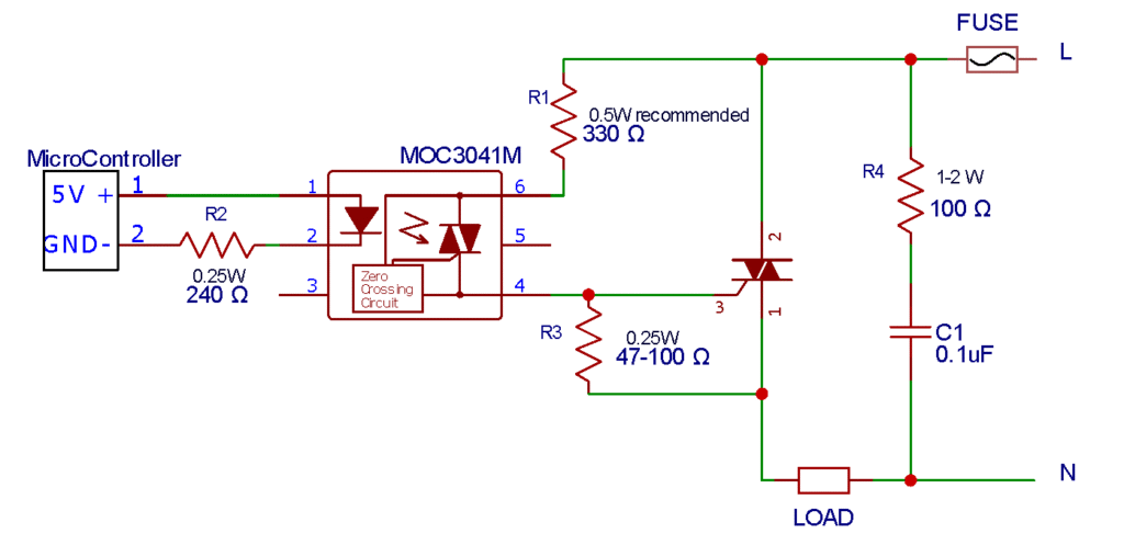
🔹 Circuit Diagram


🔹 Components Values and Recommendation
- R1
R1 is the gate-limiting resistor used to control the amount of current flowing into the gate of the external TRIAC, such as BTA16 or BTA06. Its main purpose is to protect the TRIAC by ensuring that the gate current stays within safe operating limits. The value of R1 is determined based on the peak voltage (Vp) of the AC supply. By dividing Vp by a fixed current value, typically 1 ampere for estimation purposes, you can get a quick approximation for R1. This method provides a simple way to size the resistor, especially in circuits where exact gate current isn’t critical, and it’s shown in the equation provided below. :

- R2
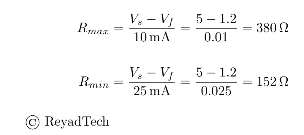
R2 its the Resistor of the Internal Led of the MOC3041/3021, it porous to limit the current, we need current from 10mA to 25mA, the led voltage typically 1.2 volt, we can extract the Value of the resistor depends on the Supply voltage(3.3v, 5v, 9v, 12v, …etc.) , for each voltage there is Rmax and Rmin
as shown below

- R3
R3 is the resistor connected between the gate and MT1 of the TRIAC. Its main purpose is to prevent false triggering by discharging any leakage current or noise that might build up on the gate. Without this resistor, the gate could stay partially charged and cause the TRIAC to turn on unexpectedly. The recommended value range for R3 is between 47 ohms and 330 ohms. Values within this range are low enough to safely drain leakage current but high enough not to interfere with the gate triggering process.
- R4 + C1
The snubber circuit in a TRIAC-based AC control setup is used to protect the TRIAC from false triggering and damage caused by sudden voltage spikes or high dV/dt (rate of voltage change). It usually consists of a resistor and a capacitor connected in series across the TRIAC’s MT1 and MT2 terminals.
A common and effective snubber configuration uses a 100Ω resistor (rated 1–2 watts) in series with a 0.1µF X2 safety capacitor. The resistor limits the current during voltage spikes, while the capacitor absorbs and smooths out the transient voltages. The 1–2W rating ensures the resistor can handle repeated surge energy without overheating. This setup is especially important when switching inductive loads like motors, relays, or transformers.
🔴 1. Leakage Current When OFF
- Description: Even when the SSR is turned off, it allows a small current (typically in milliamps) to pass through.
- Impact: Can cause unexpected behavior in sensitive loads, such as LEDs flickering or relays staying partially activated.
- Fix: Add a bleeder resistor or dummy load across the output to drain the leakage current. (it added in parallel with the load, 10W or more preferred, with AC specifics)
🔴 2. Overheating
- Description: SSRs generate heat during operation due to internal voltage drop across the TRIAC or MOSFET.
- Impact: Without proper cooling, this can lead to thermal shutdown or permanent failure.
- Fix: Use a suitable heatsink, apply thermal paste, and ensure ventilation or forced cooling if necessary.
🔴 3. False Triggering / Not Turning OFF
- Description: Caused by electrical noise, high dv/dt, or inductive load back-EMF, especially in motor or transformer loads.
- Impact: SSR turns ON by itself, or fails to turn OFF at the AC zero crossing.
- Fix: Add a snubber circuit (RC network), and if necessary, use SSRs with zero-cross detection and dv/dt immunity
