
1. Introduction
The TRIAC (Triode for Alternating Current) is a bidirectional semiconductor switch, categorized under the thyristor family. It is widely utilized in alternating current (AC) power control systems due to its capability to conduct current in both polarities upon gate triggering. The TRIAC simplifies circuit topology in AC applications such as phase control, dimming systems, and electronic switching, by enabling bidirectional conduction through a single device.
TRIACs are especially valuable in reducing the need for additional mechanical relays, as their solid-state design provides faster switching, greater reliability, and silent operation. These features make them indispensable in both consumer and industrial electronics.
2. Internal Structure and Symbolism
The TRIAC consists of a multilayer semiconductor structure made of five alternating P- and N-type regions. Electrically, it can be visualized as two SCRs (Silicon Controlled Rectifiers) connected in inverse-parallel, sharing a common gate. This configuration allows conduction in either direction depending on gate triggering.
Terminals:
- MT1 (Main Terminal 1): Reference terminal.
- MT2 (Main Terminal 2): Connected to the AC load.
- Gate (G): Control input to initiate conduction.
3. Principle of Operation
TRIACs can be triggered in four distinct quadrant modes:
- Quadrant I: MT2 positive, Gate positive relative to MT1
- Quadrant II: MT2 positive, Gate negative
- Quadrant III: MT2 negative, Gate negative
- Quadrant IV: MT2 negative, Gate positive
The conduction is initiated by a gate current and maintained until the current through the device drops below the holding current (IH).
Key Equation:
Where:
- : Voltage drop across terminals
- : Load current
- : On-state resistance of the TRIAC
4. Electrical Characteristics
| Parameter | Description |
|---|---|
| Breakover Voltage | Max voltage before uncontrolled conduction starts |
| Gate Trigger Current | Minimum current needed to turn on the device |
| Holding Current | Minimum current to keep the TRIAC in the ON state |
| On-state Voltage | Voltage across MT1 and MT2 during conduction |
| dv/dt Rating | Max rate of voltage change that the device can withstand |
A precise understanding of these parameters is critical for designing circuits that are both reliable and safe.
5. Comparative Analysis: TRIAC vs SCR
| Parameter | TRIAC | SCR |
| Conduction Mode | Bidirectional (both AC half-cycles) | Unidirectional (single AC half-cycle) |
| Gate Triggering | Positive or Negative | Positive only |
| Circuit Complexity | Simpler in AC applications | Requires bridge or anti-parallel setup |
| Application Range | AC systems only | Suitable for both AC and DC systems |
6. Typical Applications
- Light Dimmers: Adjust brightness using phase angle control
- Fan and Motor Speed Controls: Reduce power to AC motors
- Electronic Thermostats: Control heating elements
- Solid-State Relays: Enable safe switching without moving parts
- Washing Machines & Dishwashers: Timed heating and motor control
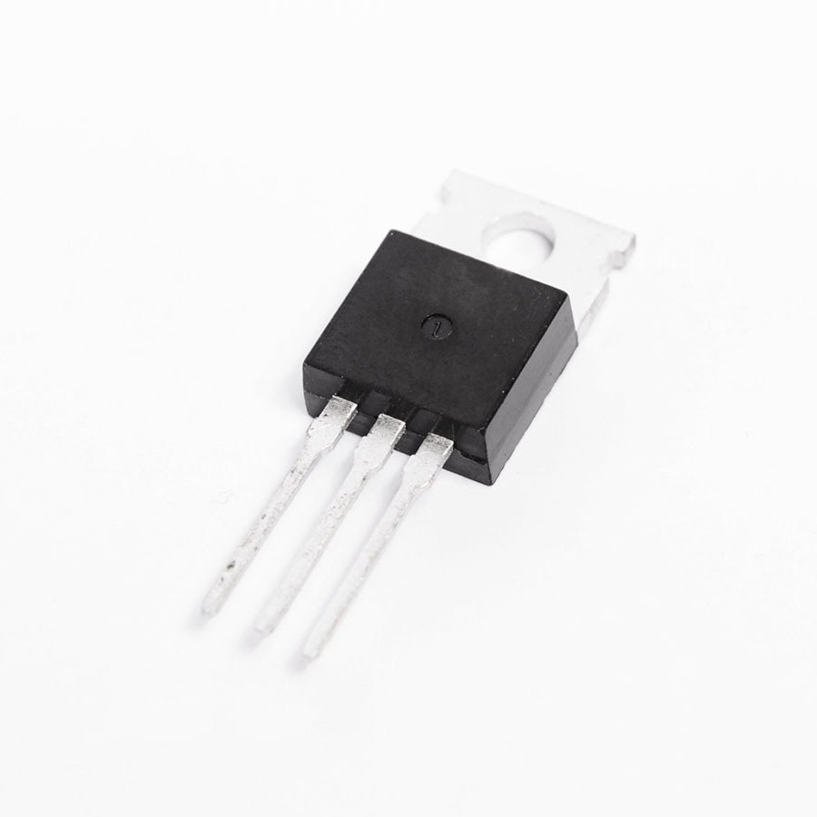
7. Case Study: BTA16 TRIAC
- Manufacturer: STMicroelectronics
- Rated Voltage: Up to 800 V
- Rated Current: 16 A
- Surge Current: 160–200 A
- Features: Electrically isolated tab, high noise immunity
The BTA16 is widely used with optoisolators like MOC3041 to ensure isolation and synchronized zero-crossing switching, minimizing EMI.
8. Design Considerations and Protection Mechanisms
To protect TRIACs from damage:
- RC Snubber: Prevents dv/dt triggering. Typically 100Ω + 0.1 µF.
- Gate Resistor: Controls gate current (100–330Ω typical).
- MOVs: Suppress voltage spikes across the TRIAC.
- Heatsink: Dissipates thermal energy due to conduction loss.
Formula for Power Dissipation:
Where:
- : Power dissipation
- : On-state voltage
- : Current through the load
9. Practical Implementation Example
Circuit Elements:
- Microcontroller (e.g., Arduino)
- MOC3041 Optoisolator
- BTA16 TRIAC
- Load (AC bulb or motor)
- Snubber RC network
This setup allows dimming or speed control using pulse timing synced with AC zero-crossing.
10. Simulation and Testing Tips
Use LTspice, Multisim, or Proteus:
- Measure trigger delay and phase control
- Simulate thermal overload under high current
- Evaluate snubber effect by adjusting capacitor/resistor values
11. Modern Alternatives and Advancements
For applications requiring higher switching speed and efficiency:
- MOSFET + H-Bridge: For efficient AC switching
- IGBT Modules: For high current industrial control
- SiC and GaN FETs: Lower losses, higher efficiency
12. References
- STMicroelectronics. “BTA16 Datasheet.” https://www.st.com
- Rashid, M. H. Power Electronics: Circuits, Devices and Applications, Pearson.
- Boylestad, R. L. Introductory Circuit Analysis, Prentice Hall.
- IEEE Xplore. Papers on TRIAC triggering and snubber design.
- Electronics Tutorials. TRIAC operation and phase control examples.
13. Conclusion
TRIACs serve as critical elements in AC power control systems due to their compactness, reliability, and bidirectional switching. Understanding their internal structure, operation quadrants, and protection requirements enables engineers to optimize circuit design for lighting, motor control, and heating systems. As newer technologies evolve, TRIACs continue to hold a firm place in medium-power, cost-sensitive applications.